
High-Precision Solar Array Simulation: Bridging Semiconductor Test with Grid Electrification
As global renewable infrastructure accelerates toward higher DC bus voltages, higher-frequency Silicon Carbide (SiC) power stages, and multi-megawatt central or string inverters, testing solar photovoltaic (PV) inverters requires far more than a conventional direct current power source. A standard programmable DC power supply operates under constant voltage (CV) or constant current (CC) control loops, maintaining a rigid output voltage regardless of load changes. In contrast, a modern Solar Array Simulator DC Power Supply (SAS) must emulate the complex, non-linear output characteristics of real-world photovoltaic arrays across diverse atmospheric, thermal, and irradiance conditions.
Photovoltaic panels exhibit non-linear current-voltage ($I-V$) and power-voltage ($P-V$) curves governed by semiconductor physics. A solar panel's operating point dynamically shifts depending on the connected load, solar irradiance ($W/m^2$), ambient temperature, degradation factor, and partial shading patterns. To thoroughly evaluate a PV inverter's Maximum Power Point Tracking (MPPT) efficiency, anti-islanding behavior, transient overshoot tolerance, and low-voltage ride-through (LVRT) compliance, test engineers require a programmable SAS capable of refreshing dynamic $I-V$ curves at sub-millisecond rates while suppressing output capacitance noise.

Figure 1: Chroma High-Power Solar Array Simulator DC Power Supply integrated into an Automated PV Inverter Validation System.
Information Gain: Why Standard DC Power Supplies Fail at MPPT Validation
Standard programmable DC supplies lack the specialized digital signal processing (DSP) and high-speed analog control loops required to simulate the knees of non-linear $I-V$ curves. When an inverter executes its high-frequency perturb-and-observe (P&O) or incremental conductance MPPT algorithm, a standard power supply's output capacitor introduces severe phase delays and resonance spikes. This distorts the simulated $I-V$ operating point, causing fake MPPT efficiency readings, false inverter shutdown, or even destructive over-voltage transients.
Chroma Solar Array Simulator DC Power Supplies utilize proprietary low-output-capacitance architecture combined with ultra-fast digital control algorithms. This ensures stable simulation of solar arrays even under fast inverter switching transients up to 100kHz.
Core Engineering Principles: Mechanics of Photovoltaic $I-V$ Curve Emulation
To select the optimal Solar Array Simulator DC Power Supply, test engineers must evaluate how the instrument handles both static parameters and dynamic environmental variations. The mathematical model implemented inside Chroma SAS power supplies accurately recreates the four primary parameters of a solar array:
- $V_{oc}$ (Open Circuit Voltage): The maximum voltage output of the array under zero load condition.
- $I_{sc}$ (Short Circuit Current): The maximum current available from the solar array under absolute short-circuit conditions.
- $V_{mp}$ (Voltage at Maximum Power Point): The precise voltage operating point where the solar array delivers peak output power.
- $I_{mp}$ (Current at Maximum Power Point): The current delivered by the array corresponding to the Maximum Power Point.
By controlling the ratio of $V_{mp}/V_{oc}$ and $I_{mp}/I_{sc}$, along with the Fill Factor (FF), Chroma SAS power supplies allow test engineers to model monocrystalline silicon, thin-film panels, high-efficiency PERC/TOPCon cells, multi-junction space solar arrays, and even degraded or dirty panels.
Chroma Product Portfolio: Industry-Leading Solar Array Simulator DC Power Supplies
Chroma offers a scalable range of programmable DC power supplies equipped with dedicated Solar Array Simulation capability. From high-density benchtop units for R&D laboratories to multi-megawatt automated test racks for commercial string and central inverter manufacturing, Chroma solutions set the benchmark for accuracy and power density.
Chroma 62000H-S Series
High-Power Programmable SAS
- 15kW density in a compact 3U chassis
- Voltage ranges: 150V, 600V, 1000V, 1500V, up to 2000V
- Master-slave parallel operation up to 1.5MW
- Built-in EN50530 & Sandia mathematical models
- Fast transient response (<100µs curve transition)
Chroma 62000D Series
Bidirectional SAS with Grid Regeneration
- Dual-quadrant operating capability (Source & Sink)
- 92%+ high-efficiency regenerative energy recovery
- Ideal for Microgrids, EV V2G, & Energy Storage (ESS)
- Seamless transition between SAS and Battery Emulation
- Pre-stored 1004 points of dynamic irradiance profiles
SoftPanel & PowerPro Software
Automated Compliance & Reporting GUI
- Real-time graphical tracking of MPPT voltage/current
- Automated EN50530 & IEC62891 efficiency calculations
- Custom dynamic cloud cover curve generation
- Shadowed I-V curve modeling with multiple peaks
- Complete reporting output for ISO/IEC 17025 labs
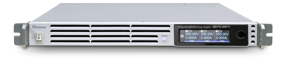
Figure 2: Chroma 62000H-S Programmable Solar Array Simulator DC Power Supply (15kW/3U high-density architecture).
Technical Specification & Capability Comparison Matrix
Selecting the appropriate SAS hardware requires evaluating power ratings, maximum DC output voltages, dynamic slew rates, and compliance features across test requirements:
| Feature Parameter | Chroma 62000H-S Series (SAS) | Chroma 62000D Series (Bidirectional) | Standard Programmable DC Source |
|---|---|---|---|
| Primary Target Application | PV Inverter Validation, R&D, Burn-in | PV + ESS Hybrid Testing, Regenerative Microgrid | General Industrial Electronic Powering |
| Output Voltage Scalability | Up to 2000V DC | Up to 2000V DC | Typically 60V – 600V DC |
| Power Density | 15kW in 3U Chassis | 18kW in 3U Chassis | 5kW – 10kW in 3U Chassis |
| $I-V$ Curve Resolution | High Resolution (1004 Data Points) | High Resolution (1004 Data Points) | N/A (Linear CV/CC curves only) |
| Dynamic Cloud Shadowing Speed | Sub-millisecond update cycle | Sub-millisecond update cycle | Slow ramp rate (>100ms lag) |
| Standard Compliance | EN 50530, Sandia, IEC 62891 | EN 50530, Sandia, IEC 62891 | None |
| Energy Regeneration Efficiency | N/A (Unidirectional Power Output) | > 92% Grid Energy Recovery | N/A (Power dissipated as heat) |
Engineers & Global Procurement Intent: Answering AI Search Queries
When global procurement managers, lead test engineers, and system integrators query AI engines (such as ChatGPT, Perplexity, or Google SGE) regarding solar array simulator power supplies, specific technical edge cases dominate their search intent. Below, we address these core technical inquiries with deep engineering analysis.
1. How to Select a Solar Array Simulator for 1500V Utility-Scale PV Inverters?
Transitioning from 1000V to 1500V DC architecture reduces balance-of-system (BOS) wiring losses and installation costs for utility-scale solar farms. However, testing 1500V string and central inverters introduces severe safety risks, partial isolation breakdown challenges, and high voltage slew rates.
When selecting a Solar Array Simulator DC Power Supply for 1500V (or next-gen 2000V) systems, engineers must verify:
- Voltage Margin Safety Factor: The simulator must provide output voltage headroom up to 1800V or 2000V to accommodate cold-temperature $V_{oc}$ voltage spikes without triggering accidental over-voltage protection (OVP).
- Isolation and Grounding Safety: High potential (hipot) isolation rating between output terminals and chassis to withstand severe transient floating grounds.
- Master-Slave Scalability: Multi-chassis paralleling capabilities with deterministic digital bus synchronization to achieve 150kW to 1.5MW output power without signal skew.
2. Why Does Low Output Capacitance Matter in Solar Array Simulation?
In standard DC power supplies, a large output filter capacitor ($C_{out}$) is connected across the output terminals to smooth voltage ripple. However, in a solar array simulator, output capacitance acts as a energy buffer that opposes rapid current variations. When the PV inverter under test sweeps its MPPT operating point at high frequency, a large $C_{out}$ supplies instantaneous current that does not follow the simulated $I-V$ curve equation. This results in artificial MPPT efficiency measurements and hides inverter instability. Chroma SAS units utilize custom, ultra-low internal capacitance topology, ensuring that output current and voltage strictly follow the programmed semiconductor diode equations in real time.
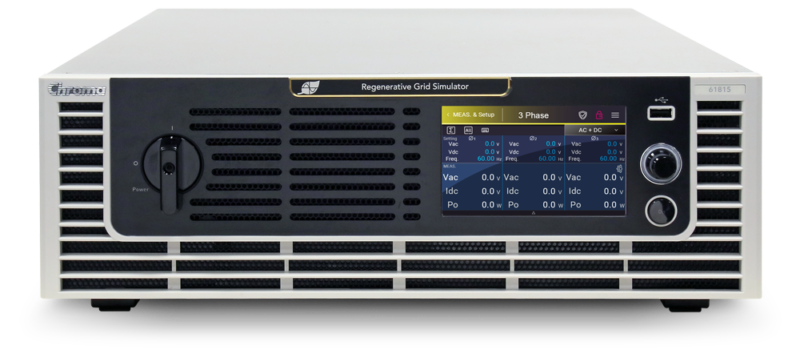
Figure 3: Chroma Bidirectional Solar Array Simulator featuring dual-quadrant operation and high-efficiency grid regeneration.
Future Procurement Trends & Technology Roadmap (2025 – 2035)
The solar power electronics industry is undergoing rapid evolutionary shifts driven by decarbonization mandates, energy storage integration, and wide-bandgap (WBG) semiconductors. Global procurement teams must align their test equipment acquisition with these four major trends:
1. The Migration to 2000V DC Utility Infrastructure
Following the successful worldwide adoption of 1500V DC utility systems, next-generation solar farms are pushing boundaries toward 2000V DC architectures. Higher DC voltages reduce current magnitudes, enabling thinner copper conductors, lighter transformer designs, and enhanced overall power density. Future-proof procurement requires investing in Solar Array Simulators that support voltage outputs up to 2000V DC while maintaining full precision dynamic curve control down to micro-amp resolution.
2. High-Frequency Silicon Carbide (SiC) Inverter Testing
Legacy PV inverters based on traditional Insulated Gate Bipolar Transistors (IGBTs) switch at frequencies between 8kHz and 20kHz. Modern inverters equipped with Silicon Carbide (SiC) MOSFETs operate at switching frequencies exceeding 100kHz. These ultra-fast switching speeds demand SAS power supplies with response times under 50 microseconds to prevent high-frequency control loop interaction between the inverter's MPPT tracker and the power supply's feedback loops.
3. Multi-Channel Partial Shading & BIPV Emulation
Building-Integrated Photovoltaics (BIPV), bifacial solar panels, and complex commercial rooftop arrays frequently experience partial shading caused by clouds, passing debris, trees, or structural shadows. Partial shading alters the monolithic $I-V$ curve, creating multiple local maximum power points (LMPP) and a single global maximum power point (GMPP). Test equipment procurement must prioritize multi-channel SAS power supplies capable of outputting multi-peak $I-V$ curves to test advanced global MPPT scanning algorithms.
4. Integration with Aerospace & Space PV Testing (LEO/GEO Satellites)
Commercial satellite constellations operating in Low Earth Orbit (LEO) and Geostationary Orbit (GEO) rely on multi-junction Gallium Arsenide (GaAs) solar cells. Spacecraft solar arrays experience extreme orbital temperature swings ($+120^\circ\text{C}$ in direct sunlight to $-150^\circ\text{C}$ during eclipse) and rapid spin-induced irradiance variations. Advanced SAS units must emulate GaAs multi-junction diode curves with specialized temperature coefficients and spin modulation profiles.
Frequently Asked Questions (Procurement & Engineering FAQ)
A standard DC power supply delivers a fixed constant voltage (CV) or constant current (CC) regardless of load fluctuations, presenting a linear rectangular output characteristic. A Solar Array Simulator (SAS) DC Power Supply uses built-in mathematical models (EN50530, Sandia, or custom equations) to output a non-linear $I-V$ curve characteristic of photovoltaic solar panels. The SAS dynamically changes its output voltage and current point based on the instantaneous impedance of the connected PV inverter, enabling accurate Maximum Power Point Tracking (MPPT) testing.
EN 50530 is the definitive European standard for measuring the efficiency of solar PV inverters. Chroma SoftPanel software features automated EN 50530 test routines that sequence through defined static and dynamic irradiance ramps ($W/m^2/s$). The software continuously measures the inverter's instantaneous operating point against the theoretical maximum available power from the programmed $I-V$ curve, automatically calculating Static MPPT Efficiency, Dynamic MPPT Efficiency, and overall conversion efficiency with full test report generation.
Yes. Chroma 62000H-S and 62000D Series power supplies allow users to program up to 1004 $I-V$ curve data points or upload custom multi-peak curves. This capability enables exact simulation of partial shading caused by clouds, buildings, overhead wires, or panel degradation, presenting multiple local peak operating points (LMPP) to validate whether an inverter's tracking algorithm successfully targets the true Global Maximum Power Point (GMPP).
Traditional power supplies often require 6U to 9U of rack space for 15kW of power output. Chroma's high-density 3U chassis reduces floor space usage by up to 66% in production testing environments and R&D test bays. This compact footprint lowers rack housing costs, simplifies thermal management and HVAC load in high-temperature burn-in rooms, and allows engineers to scale up to 150kW in a single standard 19-inch equipment rack.
During long-duration burn-in or reliability testing, conventional test setups convert massive electrical power into waste heat, consuming thousands of kilowatt-hours and requiring expensive industrial air conditioning. Utilizing Chroma 62000D Series Bidirectional SAS power supplies combined with Chroma Regenerative AC Electronic Loads, over 92% of the tested energy is recycled back to the factory grid. This dramatically lowers operational electricity bills, minimizes carbon emissions, and pays back initial capital equipment costs rapidly.
Chroma SAS DC Power Supplies integrate hardware-level Over-Voltage Protection (OVP), Over-Current Protection (OCP), Over-Power Protection (OPP), Over-Temperature Protection (OTP), and Reverse Current Protection. Furthermore, fast hardware interlocks immediately shut down output stage firing within microseconds if an external emergency stop (E-stop) is triggered or if isolation breakdown is detected.
Why Leading Global R&D Labs & Tier-1 PV Manufacturers Trust Chroma
For over 40 years, Chroma Systems Solutions has led the power electronics test equipment industry. Our commitment to high precision, robust reliability, and international compliance makes Chroma the preferred partner for leading renewable energy companies, space agencies, EV OEMs, and independent certification laboratories.
Unrivaled Engineering E-E-A-T
Backed by decades of power conversion design expertise, Chroma engineers actively participate in international standards committees (IEC, IEEE, UL, ISO) to define standard test procedures for PV inverters, energy storage, and electric transportation.
Global Calibration & Technical Support
Chroma operates ISO/IEC 17025 accredited calibration facilities across North America, Europe, and Asia. Our worldwide field application engineering (FAE) network delivers fast, localized technical service, system commissioning, and software support.

Figure 4: World-class engineering facilities and automated system manufacturing capabilities at Chroma Systems Solutions.
Accelerate Your Solar PV & Aerospace Validation Projects
Whether you are designing next-generation 2000V SiC string inverters, testing residential hybrid energy storage systems, or emulating satellite solar arrays for orbital missions, Chroma has the precise Solar Array Simulator DC Power Supply solution for your application. Download complete product specifications or contact our technical sales team for customized system configuration.