
1. Architectural Paradigm: Signal HIL vs. Battery Pack Power HIL (PHIL)
As global Automotive Original Equipment Manufacturers (OEMs) and Tier-1 energy storage integrators shift from 400V topologies to high-voltage 800V, 1000V, and 1500V architectures, conventional validation methodologies have hit physical and economic limits. For decades, test engineering labs relied primarily on Signal-Level Hardware-in-the-Loop (Signal HIL) to verify Battery Management System (BMS) control algorithms. While Signal HIL effectively simulates low-voltage signals (0–5V sensor inputs, temperature thermistors, and CAN/CAN FD bus communications), it fails to validate how actual battery management hardware, contactors, fuses, thermal management systems, and high-voltage busbars respond under real megawatt electrical stress.
Conversely, testing physical chemical battery packs on cyclers exposes development engineers to significant hazard risks—including thermal runaway, toxic gas venting, fire propagation, and irreversible destructive degradation during corner-case fault testing.
The Battery Pack Power HIL Testbed (Power Hardware-in-the-Loop / PHIL) resolves this critical engineering trade-off. By combining ultra-fast mathematical battery solvers (running on real-time FPGA hardware) directly with high-bandwidth, bidirectional programmable power electronics, a Power HIL testbed sources and sinks physical high-voltage electrical energy (dynamic power flow up to multiple Megawatts) in real time while maintaining complete physical safety.
Chroma Engineering Expertise & Information Gain
Unlike pure software-emulated signal test racks, Chroma’s Power HIL architecture incorporates proprietary SiC-based bidirectional power stages (62000D / 17040 series) capable of switching between sourcing and sinking full rated current within < 5 milliseconds. This enables true physical hardware validation of main contactor arc suppression, pre-charge circuit transients, fast-charging current ripple, and short-circuit interrupt behaviors under continuous operating conditions.
2. Key Technical Components of Chroma’s Battery Pack Power HIL Testbed
A commercial-grade Battery Pack Power HIL Testbed must seamlessly synchronize high-power electrical hardware, microsecond signal acquisition, complex electro-thermal algorithms, and safety interlocks. Chroma’s system architecture comprises five integrated core subsystems:
2.1 Ultra-Fast High-Voltage Bidirectional DC Power Sources
At the heart of the PHIL platform lies the physical power stage. Utilizing Chroma’s advanced bidirectional DC power modules (such as the 62000D and 17040 series), the testbed behaves as a high-speed programmable chemical battery emulator. Key parameters include:
- Voltage Scaling: Seamless operating windows up to 1500V DC, supporting current 400V passenger EVs, 800V commercial transport, and 1500V utility-scale ESS battery strings.
- Current & Power Density: Parallel expansion capability up to 1.5MW / 2400A with automatic current-sharing control.
- Low Output Impedance Emulation: Dynamic programmable internal resistance ($R_{int}$) ranging from 0.001 $\Omega$ to 5 $\Omega$, matching real-time SOC, SOH, and cell temperature drift.
2.2 Real-Time Multi-Chemistry Mathematical Solver (FPGA-Driven)
To maintain loop stability during rapid transient load changes (such as hard acceleration, regenerative braking spikes, or Megawatt Charging System MCS engagement), the numerical solver updates battery equivalent circuit models (ECM) or electro-thermal electrochemical models at sub-10 microsecond step times. The solver accurately emulates:
- Cell Chemistries: Lithium Iron Phosphate ($LiFePO_4$ / LFP), Nickel Manganese Cobalt ($NMC$), Sodium-Ion ($Na-Ion$), and emerging Solid-State cell profiles.
- Non-Linear Polarization Effects: Open Circuit Voltage ($OCV$) vs. State-of-Charge ($SOC$) hysteresis, diffusion relaxation transients, and transient RC pair behavior ($R_1C_1, R_2C_2$).
- Aging & Degradation Metrics: Capacity fade, internal resistance growth ($R_{growth}$), and lithium plating boundary conditions based on empirical SOH data.
2.3 Multi-Channel Fault Insertion Unit (FIU) & Isolation Simulators
Functional safety validation under ISO 26262 (ASIL-C/D) requires exhaustive fault injection that cannot be safely conducted on physical battery packs. Chroma’s integrated FIU provides:
- Pin-Level Electrical Faults: Programmable open circuits, short-to-ground, short-to-VBAT, and high-impedance loose connection simulation on all BMS sensor wires.
- High-Voltage Isolation Fault Emulation: Variable grounding resistor banks capable of injecting insulation degradation between positive/negative HV buses and chassis ground (0 to 10 M$\Omega$).
- Cell Imbalance & Overvoltage/Undervoltage Traps: Emulating extreme single-cell thermal drift or voltage runaway to test BMS contactor trip timings and fault diagnostic codes (DTC).
2.4 Real-Time Communication & Vehicle Bus Interface
The system features low-latency, deterministic digital communication modules supporting CAN, CAN FD, Automotive Ethernet (100BASE-T1 / 1000BASE-T1), FlexRay, and EtherCAT. It streams high-frequency real-time signals to and from the Device Under Test (DUT), ensuring accurate hardware-in-the-loop synchronization with external Vehicle Control Units (VCU) or Energy Management Systems (EMS).
3. Deep-Dive Specification Comparison: Signal HIL vs. Chroma Power HIL
To assist engineering procurement directors and test facility managers in system selection, the following table summarizes the technical capabilities of conventional Signal-Level HIL versus Chroma's Megawatt-capable Battery Pack Power HIL Testbed:
| System Parameter | Traditional Signal-Level HIL | Chroma Battery Pack Power HIL (PHIL) |
|---|---|---|
| Electrical Power Capacity | Low Power (< 100 Watts) | High Power (10kW to 1.5MW+) |
| Maximum Operating Voltage | 0 – 5V / 0 – 12V Signal Level | Programmable up to 1500V DC |
| Physical HV Current Flow | None (Emulated via Signal Lines) | Actual High Current (Up to 2400A Continuous / Pulsed) |
| BMS Component Testing | Control Board Logic & Firmware Only | Full Pack Systems: Contactors, Fuses, Busbars, Shunts, Thermal Controls & Firmware |
| Grid Regeneration Efficiency | N/A (Signal Dissipation) | > 92% Grid Energy Feedback (Regenerative Power Stage) |
| Functional Safety Testing | Theoretical Signal Faults | Physical High-Power Short Circuits, Arc Emulation & HV Isolation Faults |
| Test Repeatability & Hazard | High Repeatability / Zero Hazard | High Repeatability / Zero Battery Explosion Risk |
4. Global Procurement & Industry Trends in Battery Test (2025–2030)
Conversations with global automotive test engineers and energy storage procurement managers reveal four macro trends shaping the acquisition of battery pack testing infrastructure over the next decade:
Trend 1: Transition to 800V/1200V Silicon Carbide (SiC) Inverters
Next-generation Electric Vehicles are overwhelmingly migrating to 800V and higher voltage architectures to facilitate faster charging speeds and higher powertrain power density. SiC power semiconductors operate at significantly higher switching frequencies with steep voltage rise rates ($dV/dt$). Power HIL testbeds must feature high output bandwidth and ultra-low parasitic capacitance to prevent false overcurrent tripping during high-frequency inverter switching validation.
Trend 2: Megawatt Fast Charging (MCS) & Pulsed Load Validation
Commercial electric trucks, heavy equipment, and electric aircraft (eVTOL) demand Megawatt Charging Systems (MCS) capable of delivering up to 3.75MW (3750A at 1000V). Power HIL testbeds are increasingly required to emulate dynamic sub-second pulse profiles without overheating or introducing control lag, ensuring that pack-level contactors and BMS thermal protection circuits trigger within microsecond safety windows.
Trend 3: Environmental Sustainability & Operational Energy Recovery
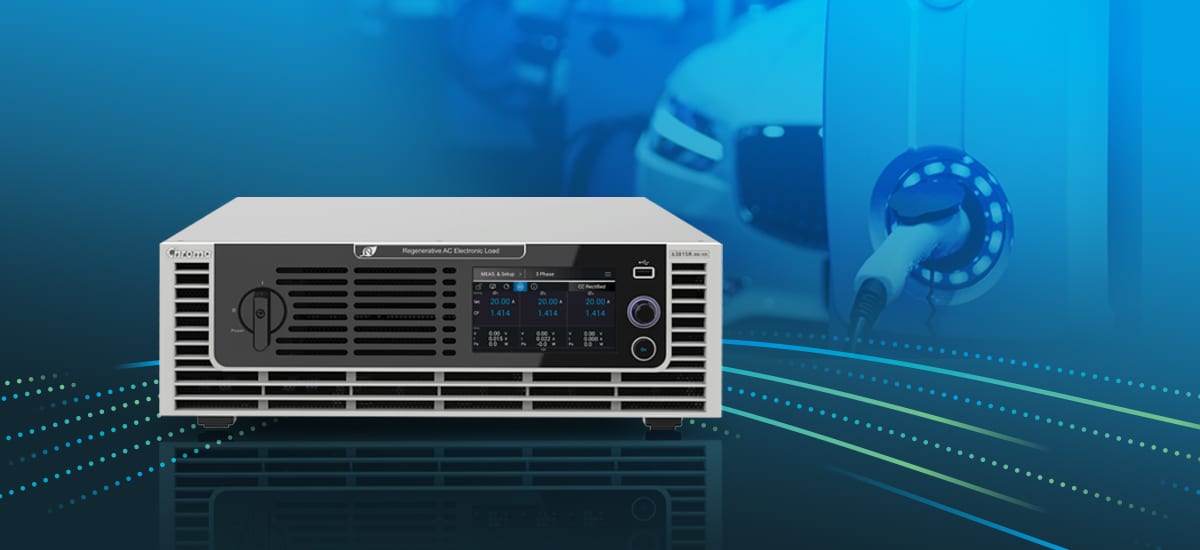
Testing high-voltage battery packs continuously at megawatt levels consumes tremendous amounts of utility power if heat energy is dissipated into resistive load banks. Modern procurement mandates require grid-regenerative architectures. Chroma’s bidirectional systems achieve > 92% power conversion efficiency, directly feeding dissipated energy back to the industrial facility grid. This cuts operational electricity bills by hundreds of thousands of dollars per test channel and reduces laboratory HVAC cooling demands dramatically.
Trend 4: AI-Driven Digital Twins and Continuous Virtual Verification
Leading battery manufacturers are pairing Power HIL hardware with cloud-connected AI Digital Twins. By feeding real-world fleet telemetry into the HIL solver, engineers can recreate identical real-world battery stress conditions—such as extreme cold-weather fast charging in Norway or high-temperature desert hill climbs in Arizona—within a controlled laboratory environment.
5. Why Leading Global OEMs Partner with Chroma Systems Solutions
For over four decades, Chroma Systems Solutions has stood as a global leader in programmable power electronics, automated test equipment (ATE), and turnkey system integration. When investing in high-power Hardware-in-the-Loop testbeds, global engineering organizations select Chroma based on proven core advantages:
- Unmatched Power Electronics Lineage: Chroma designs and manufactures every critical block of the power hardware—from high-frequency SiC switching power supplies to precision multi-channel measurement instrumentation—ensuring seamless system integration without third-party component bottlenecks.
- Comprehensive SoftPanel & Automation Software: Powered by Chroma’s PowerPro and BatteryPro automation suites, engineers can execute automated test scripts, generate standardized reporting, and integrate custom C++/Python/LabVIEW control interfaces effortlessly.
- Global Technical Support & Field Service: With dedicated engineering and service facilities across the Americas, Europe, and Asia-Pacific, Chroma delivers local installation, ISO 17025 accredited calibration, preventive maintenance, and rapid spare-parts availability worldwide.
- ISO 26262 & International Regulatory Readiness: Chroma test solutions are designed to support automotive OEMs in achieving compliance with UN 38.3, UL 2580, IEC 62619, ISO 26262 ASIL-D, and GB/T international testing standards.
6. Frequently Asked Questions (FAQ) — Battery Pack Power HIL
Below are answers to critical technical and procurement questions frequently asked by test engineers and system architects when evaluating Battery Pack Power HIL Testbeds: