
High-Precision Multi-Channel Battery Cell Simulator for Advanced BMS HIL Validation
Accelerate EV and BESS battery management system development with isolated multi-channel cell voltage sourcing, bidirectional active balancing emulation, fault injection, and real-time hardware-in-the-loop (HIL) dynamics.
Why Specialized Multi-Channel Battery Cell Simulators Are Mandatory for Modern BMS Testing
As global electric vehicle (EV) architectures transition from standard 400V battery buses to high-efficiency 800V and 1200V powertrains, and as commercial battery energy storage systems (BESS) expand into multi-megawatt installations, the safety-critical role of the Battery Management System (BMS) has become paramount. Modern BMS controllers are required to perform ultra-precise State of Charge (SoC), State of Health (SoH), and State of Power (SoP) estimations while maintaining real-time over-voltage, under-voltage, thermal runaway protection, and passive/active cell balancing.
Testing BMS hardware using real lithium-ion battery cells in a development laboratory presents severe safety hazards, environmental control challenges, and repeatable baseline issues. Real cells cannot easily recreate dangerous corner cases—such as individual cell micro-short circuits, thermal runaway initiation, sensor wire disconnects, or extreme ambient temperature SOC mismatches—without destroying physical assets. Conversely, using conventional off-the-shelf programmable multi-channel DC power supplies fails because standard power supplies cannot sink current (required during active balancing testing), lack high common-mode isolation across series-connected stacks (resulting in ground loops), and lack sub-millisecond dynamic impedance (ESR) response.
Critical Information Gain: Cell Simulator vs. Standard DC Power Supply
A true Multi-Channel Battery Cell Simulator is engineered specifically to function as an isolated, four-quadrant, low-output-impedance voltage source. Unlike general-purpose programmable power supplies, each channel can independently source current (simulating cell discharge feeding into BMS measurement circuits) and sink current (simulating active balancing currents or charger injection), while emulating dynamic Equivalent Series Resistance (ESR) in micro-seconds to mirror real lithium-ion cell chemistry behaviors under dynamic transient loads.
High-Density Channel Modular Architecture
Chroma multi-channel battery cell simulator hardware utilizes modular, rack-mountable card architectures designed to emulate stack voltages exceeding 1,000V DC across dozens or hundreds of series-connected cell channels. Each channel is equipped with independent 16-bit DACs and high-speed ADCs to guarantee independent control and measurement without crosstalk.
- Independent Channel Ground Isolation: High-dielectric isolation barriers prevent crosstalk and ground loops across high-series cell stacks up to 1000V DC working voltage.
- Bidirectional Current Sinking & Sourcing: Supports continuous bidirectional current flow per channel to thoroughly test passive resistor bleed balancing and dynamic active inductive balancing networks.
- Integrated Hardware Fault Injection (FIU): Physical relays per channel allow automated simulation of open-circuit sense wire faults, short-circuits between adjacent cells, and polarity inversion scenarios.
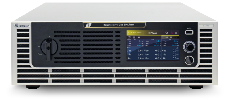
0.01% Voltage Precision
Delivers microvolt-level setpoint resolution (<100μV) essential for testing high-accuracy LFP (Lithium Iron Phosphate) cell chemistry BMS units where the OCV-SoC voltage curve is extremely flat.
Dynamic ESR Emulation
Programmable internal cell resistance per channel (0 to 1,000 mΩ) allows real-time emulation of cell aging, cold-weather internal resistance spikes, and internal degradation during dynamic current pulses.
EtherCAT & CAN Bus HIL
Deterministic communication interface support enables seamless synchronization with dSPACE, NI VeriStand, RT-LAB, and Chroma Power HIL test rigs with loop refresh rates under 1 millisecond.
Chroma Multi-Channel Battery Cell Simulator Product Lineup
Engineered for automotive R&D facilities, battery pack manufacturers, and aerospace validation labs, Chroma’s multi-channel battery cell simulators deliver uncompromised precision, modular scaling, and integrated protection. Below is an overview of our benchmark hardware configurations for enterprise BMS validation.
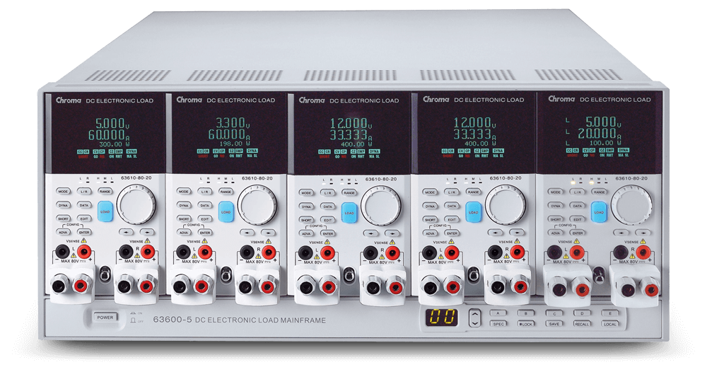
Enterprise BMS Validation Workstation Integration
Chroma multi-channel cell simulators seamlessly fit into full-scale BMS Power HIL Testbeds. By combining high-density cell simulator cards with NTC temperature sensor emulators, digital I/O modules, fault injection units, and high-voltage traction pack power supplies, engineering teams can build turn-key automated test environments compliant with ISO 26262 functional safety standard requirements up to ASIL-D.
Key Engineering Specifications Matrix
Review the primary operational parameters of Chroma’s multi-channel cell simulator series designed for high-precision battery cell modeling:
| Parameter / Specification | Standard Precision Module | High-Current Active Balancing Module | High-Voltage Stack Simulation Unit |
|---|---|---|---|
| Number of Channels per Frame | 12 / 16 Channels | 8 / 12 Channels | Up to 192 Channels (Expandable) |
| Voltage Output Range per Channel | 0 to 5 V DC / 0 to 10 V DC | 0 to 5 V DC | 0 to 5 V DC (Up to 1200V Total Stack) |
| Voltage Accuracy | ±(0.01% + 0.01% F.S.) | ±(0.02% + 0.02% F.S.) | ±(0.015% + 0.015% F.S.) |
| Current Source / Sink Capacity | ±1 A / ±3 A per channel | ±5 A / ±10 A peak per channel | ±2 A continuous per channel |
| Current Measurement Accuracy | ±(0.02% + 0.02% F.S.) | ±(0.05% + 0.05% F.S.) | ±(0.03% + 0.03% F.S.) |
| Programmable Output Impedance (ESR) | 0 to 1,000 mΩ (1 mΩ res) | 0 to 500 mΩ (0.1 mΩ res) | 0 to 2,000 mΩ (1 mΩ res) |
| Channel-to-Channel Dielectric Isolation | 1,000 V DC Isolation | 1,000 V DC Isolation | 1,500 V DC Isolation |
| Transient Response Time | < 100 μs (10% to 90% step) | < 150 μs | < 200 μs |
| Communication Interfaces | EtherCAT, Ethernet, CAN, USB | EtherCAT, CAN FD, RS-485 | EtherCAT, Ethernet (SCPI commands) |
Future Procurement & Technology Trends in Battery Cell Simulation (2026–2035)
The global test and measurement landscape for energy storage and electromobility is undergoing a profound transformation. Procurement officers and test engineering leads must evaluate multi-channel cell simulator investments not only against current lithium-ion battery validation requirements, but also against next-generation cell chemistries and software-defined vehicle architectures.
1. Transition to 800V/1200V Architecture & Ultra-High Channel Isolation Requirements
Automotive OEMs are aggressively migrating passenger vehicles, heavy trucks, and electric aircraft (eVTOL) from 400V systems to 800V, 1000V, and 1200V battery architectures to enable 350kW+ ultra-fast charging. Higher operating voltages exponentially increase common-mode voltage stress across BMS IC isolation barriers. Future procurement specifications for cell simulators require higher galvanic isolation ratings (minimum 1,000V DC to 1,500V DC channel-to-chassis and channel-to-channel) to guarantee long-term system stability without insulation breakdown or measurement drift during multi-channel stack simulation.
2. Solid-State Battery (SSB) & Advanced Chemistry Emulation
Next-generation solid-state lithium-metal batteries and sodium-ion (Na-Ion) cells exhibit dramatically different electrochemical dynamic profiles compared to conventional NMC or LFP cells. Solid-state batteries display distinct interface resistance variations based on pressure, state of charge, and rapid thermal cycles. Modern multi-channel cell simulators are evolving from simple fixed-voltage outputs to dynamic non-linear real-time math engine execution. Advanced test software can now execute dynamic OCV-SoC curves with real-time hysteresis, charge-transfer resistance emulations, and solid-electrolyte interphase (SEI) growth modeling at millisecond refresh rates.
3. AI-Driven Hardware-in-the-Loop (HIL) & Digital Twin Synchronization
Automotive software complexity is shifting toward centralized zonation E/E architectures. BMS software updates are continuously deployed via Over-The-Air (OTA) updates. Consequently, cell simulators must seamlessly integrate into continuous integration and automated software testing toolchains (CI/CD). Artificial intelligence algorithms generate complex real-world drive cycle profiles (e.g., WLTP, US06, extreme fast-charge stress curves) combined with random single-cell micro-fault injection. The multi-channel simulator acts as the real-time hardware execution interface for cloud-based Digital Twin models of the battery pack.
4. High-Current Active Balancing Test Requirements
To preserve state-of-health and maximize usable energy capacity in massive BESS container units, BMS designs are increasingly using active cell balancing circuits (flyback, capacitive, or inductive energy transfer) running at balancing currents from 2A up to 10A per cell. Multi-channel battery cell simulators must feature fast bidirectional four-quadrant power stages capable of absorbing energy without voltage overshoot, ensuring BMS active balancing control loops can be validated under dynamic load conditions.
Enterprise Advantages & Unmatched Reliability (E-E-A-T)
With over four decades of expertise in power conversion, automated test equipment, and precision energy storage validation, Chroma Systems Solutions is recognized worldwide as an authoritative partner for top-tier automotive OEMs, Tier-1 automotive suppliers, research laboratories, and megawatt BESS integrators.
Metrological Precision & NIST Traceability
Every Chroma multi-channel battery cell simulator undergoes rigorous calibration using ISO/IEC 17025 accredited calibration procedures with direct traceability to NIST (National Institute of Standards and Technology). Our commitment to high accuracy guarantees that your BMS state-of-charge calculation algorithms, cell balancing thresholds, and analog-to-digital converter (ADC) sampling circuits are validated against verified gold standards.
- Ultra-Low Noise Output: Ripple and noise ratings below 1 mV RMS prevent external electrical noise from corrupting high-sensitivity BMS voltage sense lines.
- Hardware-Level Safety Interlocks: Integrated emergency shutdown (EPO), hardware over-voltage protection (OVP), over-current protection (OCP), and reverse-polarity safeguards preserve expensive BMS prototype hardware.
- Turnkey Hardware-in-the-Loop Integration: Native support for Chroma CaptivATE, PowerPro software suites, and open-source APIs (Python, LabVIEW, C++, MATLAB/Simulink) streamlines test automation.
Frequently Asked Questions About Multi-Channel Battery Cell Simulators
Below are technical answers to common queries raised by procurement teams, test lab directors, and BMS hardware engineers when selecting cell simulation hardware.
Have specific technical questions for your upcoming test program?
Inquire Now