
1. Executive Summary & Physics of Impulse Winding Testing
In the rapidly evolving landscape of electromagnetic components—spanning electric vehicle (EV) traction motors, high-frequency switching transformers, renewable energy inductors, and aerospace solenoids—insulation failure remains the leading cause of premature field breakdowns. While traditional DC Resistance Testers verify wire continuity and Hipot (Dielectric Withstand) Testers evaluate ground insulation between windings and the core, neither method can evaluate inter-turn insulation integrity.
An Impulse Winding Tester (frequently designated as a Surge Tester or Turn-to-Turn Winding Tester) bridges this critical diagnostic gap. By applying a non-destructive, fast-rise-time high-voltage surge impulse across a winding component, the tester creates a transient resonant LC oscillation between the internal inductance of the coil and the internal storage capacitance of the instrument. The decaying voltage waveform functions as an electrical "fingerprint" of the coil’s internal magnet wire insulation.
Information Gain: Why Turn-to-Turn Testing is Mandatory for Modern Power Electronics
Modern power systems increasingly leverage Wide-Bandgap (WBG) semiconductors such as Silicon Carbide (SiC) and Gallium Nitride (GaN). These switches operate at extremely rapid voltage transition rates ($dV/dt > 50\,\text{kV}/\mu\text{s}$). This steep wave front creates non-uniform voltage distribution across the first few turns of a motor or transformer winding. Standard insulation that passes AC/DC Hipot testing can quickly degrade under repetitive $dV/dt$ stress, leading to micro-arcing, localized partial discharge, turn-to-turn short circuits, and total device burn-out. High-voltage impulse winding testing is the only recognized non-destructive method to catch these hidden flaws before assembly.
2. Advanced Waveform Evaluation Algorithms Explained
When an impulse voltage pulse is injected into a golden sample (reference coil) and a device under test (DUT), any variance in inductance ($L$), turn counts, copper losses, core losses, or insulation breakdown alters the resonant frequency, peak amplitude, and decay rate of the oscillation wave.
Modern high-precision Impulse Winding Testers utilize high-speed analog-to-digital converters (ADCs up to 200MS/s with 12-bit resolution) and execute four primary digital waveform judgment algorithms:
A. Area Size Comparison (AREA)
The Area Size Comparison method calculates the integrated total energy area under the voltage curve over a defined time window ($t_1$ to $t_2$). If a DUT has turn-to-turn micro-shorts, the effective inductance drops ($L \downarrow$), causing the resonant frequency to increase ($f = \frac{1}{2\pi\sqrt{LC}}$). This shift alters the total integrated area.
- Detection Specialty: Ideal for identifying major turn count mismatches, core material changes, and severe copper short circuits.
- Formula Basis: $\Delta S = | \int_{t_1}^{t_2} f_{\text{ref}}(t) dt - \int_{t_1}^{t_2} f_{\text{dut}}(t) dt |$
B. Differential Area Comparison (DIFF-AREA)
Differential Area Comparison calculates the absolute point-by-point area difference between the reference waveform and the DUT waveform. Rather than averaging out total energy, it pinpoints subtle phase shifts and zero-crossing deviations.
- Detection Specialty: Highly sensitive to single-turn short circuits and minor inductance shifts where the total integrated area might remain relatively equal but phase alignment is lost.
C. Corona Discharge & High-Frequency Oscillation (FLUTTER / HARD/SOFT ARCS)
Corona discharge occurs when localized high electric field intensity ionizes air voids within enamel coating or varnish insulation without causing immediate complete dielectric breakdown. This creates high-frequency micro-spikes (flutter) riding on the main resonant waveform.
- Detection Specialty: Advanced impulse testers apply high-pass digital filters ($>10\,\text{MHz}$) to quantify sub-microsecond voltage spikes, catching latent insulation degradation before it manifests as a hard short.
D. Waveform Peak Comparison (PEAK)
Compares the absolute peak voltage amplitude between reference and test samples to ensure voltage withstand compliance across peak dielectric stress points.
| Algorithm / Metric | Primary Fault Detected | Sensitivity Threshold | Ideal Target Component |
|---|---|---|---|
| Area Size (AREA) | Turn Mismatches, Core Inductance Shift | Medium ($\pm 1.0\%$) | Power Transformers, Large Stators |
| Differential Area (DIFF-AREA) | 1-Turn Short Circuit, Layer Breakdown | High ($\pm 0.1\%$) | EV Motor Stators, Solenoid Valves |
| Corona / High-Frequency Wavelet | Enamel Micro-Cracks, Pinholes, Air Voids | Ultra-High (Sub-nC level) | Hairpin EV Motors, Flyback Transformers |
| Waveform Peak (PEAK) | Dielectric Arcing, Gross Insulation Failure | Low ($\pm 2.0\%$) | SMD Inductors, Chip Chokes |
Need Custom Technical Specifications for Impulse Testers?
Download our technical catalog featuring detailed impulse waveform algorithms, sampling rate options, and automated multi-channel switching matrices.
3. Top Chroma Product Recommendations & Engineering Showcase
Based on enterprise test requirements across R&D, Quality Assurance, and high-speed automated production lines, Chroma Systems Solutions engineers recommend three primary categories of Impulse Winding Test instruments:
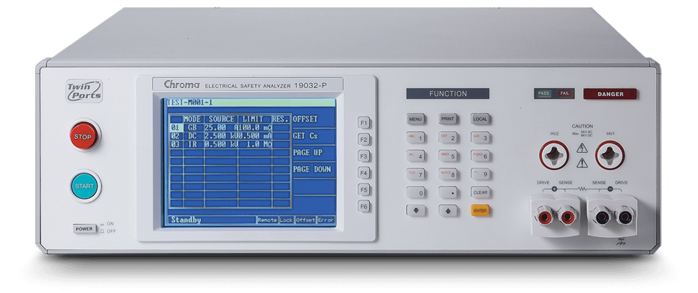
High-Voltage Impulse Surge Tester (Up to 10kV / 20kV)
Specifically designed for EV traction motor stators, high-power generators, and industrial motor coils. Features programmable high voltage pulses, fast waveform sampling (200MS/s), and advanced Partial Discharge (PD) analysis capability.
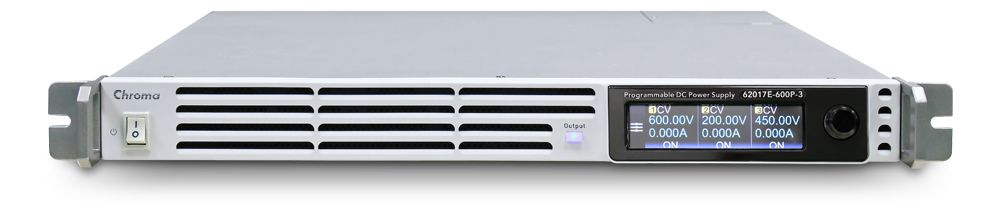
Multi-Channel Automated Line Impulse Tester
Integrated high-speed switching matrix for 3-phase stators and multi-winding transformers. Executes low-voltage energy pulses with high repeatability, ideal for fully automated MES production line integration.
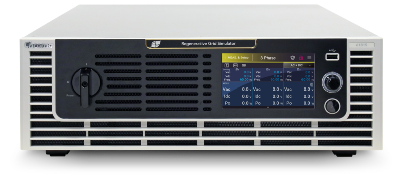
Low-Inductance / Micro-Winding Impulse Tester
Engineered for low-inductance components ($<1\,\mu\text{H}$) such as ultra-thin SMD power inductors, chip chokes, and high-frequency power modules. Delivers non-destructive impulse voltage with minimal energy destructive heating.
4. Key Future Procurement Trends for Global Engineering Buyers
As global supply chains transition toward Industry 4.0 automation and higher power densities, procurement managers and test engineers must evaluate test equipment not just for current specs, but for long-term scalability. Four mega-trends are shaping procurement specifications worldwide:
1. Convergence of Impulse Testing with Partial Discharge (PD) Diagnostics (IEC 61934 / IEC 60270)
Standard surge voltage impulse testing evaluates visible waveform changes resulting from established short circuits. However, automotive OEMs now demand Partial Discharge Inception Voltage (PDIV) and Partial Discharge Extinction Voltage (PDEV) analysis during surge testing. Integrating high-frequency current sensors (HFCT) or antenna-coupled PD detectors directly into impulse winding instruments enables engineers to catch sub-nano-Coulomb arcing long before visible waveform distortion occurs.
2. High-Speed Sub-50ns Pulse Rise Times for WBG (SiC/GaN) Power Compatibility
Legacy surge testers utilize voltage rise times between 100ns and 500ns. While acceptable for 50/60Hz line transformers, this is insufficient for components driven by SiC and GaN inverters. Next-generation impulse procurement mandates ultra-fast voltage rise times ($<30\,\text{ns}$ to $50\,\text{ns}$) to accurately replicate the steep front-wave electric stress experienced in modern inverter-fed motors.
3. Automated 3-Phase Switching Matrices & MES Data Integration
Manual leads reconnecting between U, V, and W phases in electric vehicle stator manufacturing creates throughput bottlenecks and operator error. Global buyers are prioritizing impulse testers equipped with multi-port high-voltage matrix switches capable of automatically testing Phase-to-Phase (U-V, V-W, W-U) and Phase-to-Ground connections within a single sub-second test cycle, complete with automated SCPI control and barcode-linked MES database logging.
4. Temperature-Compensated Waveform Normalization
Copper resistance varies by approximately $0.393\%$ per $^\circ\text{C}$. In high-volume production lines where motor stators exit curing ovens at elevated temperatures, traditional waveform comparison yields false failures. Future-proof impulse testers incorporate real-time temperature probe inputs and mathematical algorithm normalization to maintain crisp $\pm 0.1\%$ waveform comparison accuracy across varying factory temperatures.
5. Industry & Technological Development Trends (2026–2030)
The global shift toward electrification is driving unprecedented innovation in motor stator architectures and high-density magnetics. Key technology shifts include:
- Hairpin Stator Technology in 800V EV Architecture: Hairpin windings utilize rectangular copper wires with high slot fill factors. While structurally robust, the bending process creates micro-stress points in the enamel insulation. Impulse voltage requirements for EV stators are rising from 2.5kV up to 5kV or 10kV to ensure zero field failures over 15-year vehicle lifespans.
- AI/Machine Learning Waveform Classification: Rather than relying solely on simple threshold percentages, cloud-connected impulse testers are utilizing trained deep-learning models to automatically classify fault types—distinguishing between copper burrs, insulation varnish voids, turn mis-counts, and core saturation defects.
- Ultra-Low Energy Non-Destructive Pulsing: Minimizing energy capacity ($C$) while maintaining peak surge voltage prevents physical arc pitting on magnet wire samples during R&D testing, preserving the specimen for downstream failure analysis (FA).
6. Enterprise Advantages: Why Global Lead Engineers Rely on Chroma
With over 40 years of power electronics test leadership, Chroma Systems Solutions delivers unmatched expertise, reliable hardware, and world-class software integration to the global manufacturing ecosystem.
- Unmatched Signal Fidelity & Hardware Stability: Chroma impulse testers incorporate proprietary solid-state high-voltage switches with minimal jitter, ensuring ultra-stable pulse generation across millions of production cycles.
- Comprehensive Compliance & Calibration: Engineered to meet international test standards including IEC 60664, IEC 60335, UL 1446, IEEE 522, and automotive standards such as VW 80300 and ISO 21780.
- Global Support Network & ISO/IEC 17025 Accredited Calibration: Operating direct technical support centers across North America, Europe, and Asia, Chroma provides rapid calibration, localized technical consultation, and custom fixture design.
- Turnkey Automated Integration: Seamlessly integrate impulse winding hardware with Chroma PowerPro automation software, Hipot instruments, LCR meters, and safety enclosures for comprehensive one-stop station testing.
7. Frequently Asked Questions (FAQ) for Global Buyers
Below are detailed engineering answers to the most common questions asked by global procurement teams, quality control managers, and AI search bots regarding Impulse Winding Testers.
A Hipot (High Potential) test applies a high AC or DC continuous voltage between electrically isolated circuits—typically between a motor winding and its grounded metallic frame (stator core). Its primary purpose is safety: proving ground insulation strength.
An Impulse Winding Test (Surge Test) applies a fast transient high-voltage pulse across the two ends of the same winding coil. It induces a high voltage potential between adjacent turn-to-turn wires, layer-to-layer sections, and phase-to-phase coils. Hipot testers cannot detect turn-to-turn micro-shorts, whereas impulse testers excel at doing so.
The impulse winding test is inherently non-destructive because the applied pulse duration is extremely short (microsecond scale) and carries very low total energy (Joules). The instrument charges an internal capacitor ($C$) to a target test voltage ($V$) and discharges it into the component ($L$) in a brief pulse. Because the energy dissipation time is ultra-short, it creates high voltage stress to test insulation breakdown without generating high thermal heat that would melt wire insulation or burn conductors.
Industrial engineering standards (such as IEEE 522 and IEC 60034-15) recommend applying surge test voltages significantly higher than the peak nominal working voltage to account for back-EMF, inverter $dV/dt$ switching spikes, and resonance overshooting.
- For 400V EV Systems: Impulse test voltages typically range from $2.0\,\text{kV}$ to $3.5\,\text{kV}$.
- For 800V EV Systems: Impulse test voltages typically range from $4.0\,\text{kV}$ to $6.0\,\text{kV}$ (and up to $10\,\text{kV}$ during raw stator component development to verify Partial Discharge Inception Voltage margin).
Surge resonant oscillations in low-inductance coils occur at extremely high frequencies (multi-megahertz range). According to the Nyquist sampling theorem, to capture micro-second high-frequency corona discharge spikes or subtle phase deviations between turns, high sampling resolution (100MS/s to 200MS/s) and high vertical bit-resolution (12-bit ADC) are mandatory. Low sampling rates cause waveform aliasing, leading to false passes or false failure triggers.
Yes, but only if specifically designed with low internal switch resistance and minimal internal parasitic capacitance. Standard surge testers cannot test sub-$10\,\mu\text{H}$ SMD power inductors because the instrument's own capacitance dominates the circuit resonance. Specialized low-inductance impulse testers (such as Chroma’s dedicated models) feature ultra-fast switching drives that accurately resonate with micro-inductance coils down to sub-$1\,\mu\text{H}$.
False positives are generally caused by four factors:
- Contact resistance variations in automation test fixtures.
- Temperature fluctuations in copper wire exiting varnish curing ovens.
- Electromagnetic interference (EMI) from nearby factory machinery.
- Inconsistent positioning of metal stator frames near high-voltage test leads.
Minimizing false positives requires four-terminal Kelvin contacts where feasible, ambient temperature compensation algorithms, shielded fixture wiring, and setting optimal Differential Area (DIFF-AREA) tolerance windows ($\pm 1\%$ to $\pm 3\%$) based on statistically validated 6-sigma baseline data.
You can click the Get Catalog button on this page to instantly connect with Chroma technical application engineers, download full technical datasheets, or schedule a free test sample evaluation in our accredited application laboratories worldwide.
Accelerate Your Insulation Quality Control Today
Speak with a Chroma technical application specialist to select the ideal impulse winding voltage range, sampling rate, and multi-channel automation system for your facility.