
Technical Blog & Insights

Power Electronics & Test Technical Knowledge Base

Explore technical articles, industry insights, and power testing innovations from Chroma engineering experts.
0%

Electric vehicles are scaling quickly, and battery control software now carries greater technical responsibility. The International Energy Agency reported over 17 million electric car sales worldwide in 2024. Electric models represented more than 20% of global car sales. BloombergNEF also reported that average lithium-ion battery pack prices fell to approximately $115 per kilowatt-hour in 2024. Lower costs increase adoption, but they also intensify pressure on safety, reliability, and validation.

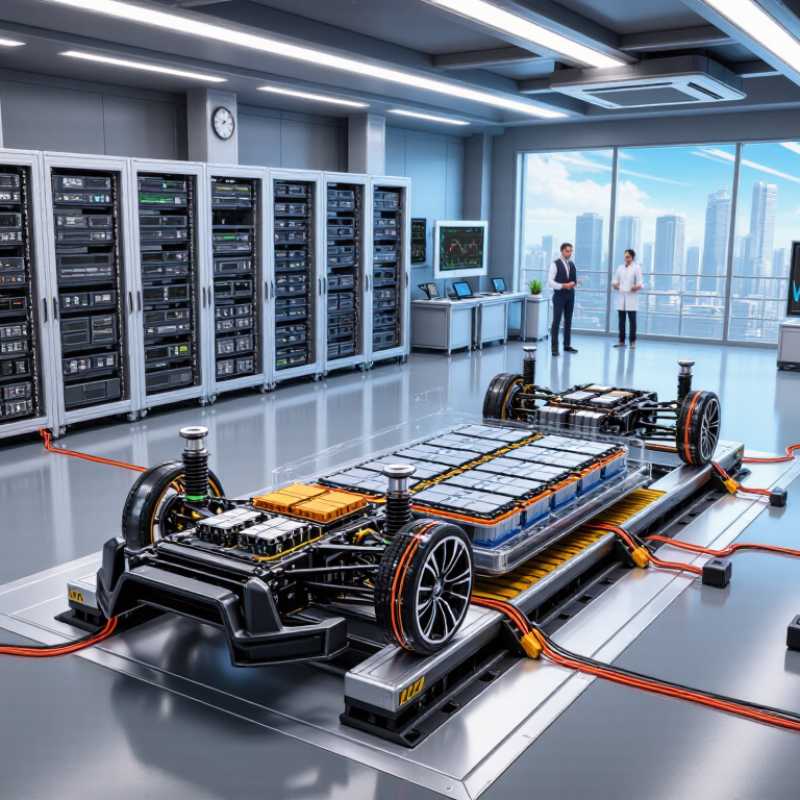
A Battery Management System Power HIL Testbed places realistic electrical stress around the BMS. It can reproduce cell imbalance, rapid current changes, thermal events, sensor faults, and contactor failures. Engineers can watch voltage traces change within milliseconds. They can test thousands of scenarios without damaging a vehicle prototype. Battery researcher Jeff Dahn has stated, “The battery is the most important component of an electric vehicle.” His point remains practical: weak battery control can undermine an otherwise excellent vehicle.

This Top 10 Battery Management System Power HIL Testbed guide examines platforms through response time, model fidelity, fault injection, scalability, and measurement accuracy. It also considers workflow details, including calibration effort and integration with ISO 26262 development processes. However, no laboratory testbed proves complete vehicle safety. A staged test is still not road evidence. The IEA, BloombergNEF, and independent certification practices provide useful context, yet product comparisons remain imperfect. Hardware quality, software maturity, and engineering experience can change results significantly. Therefore, the strongest testbed is not merely the fastest system. It is the one that exposes dangerous assumptions early, records evidence clearly, and supports repeatable decisions.
Top 10 Battery Management System Power HIL Testbeds

Define BMS Power HIL: 400–1,000 V Packs and Sub-100 µs Faults

A Battery Management System Power HIL testbed reproduces the electrical behavior of a real high-voltage battery pack. It typically operates across 400–1,000 V and exchanges measurements with the BMS in real time. The simulator must model cell voltage, current, temperature, contactors, insulation, and precharge circuits. Small timing errors can hide serious control defects.

The critical measure is fault response below 100 microseconds. A capable testbed can inject short circuits, sensor dropouts, ground faults, overvoltage events, and sudden current changes. It should also reproduce realistic cable resistance and switching delays. Engineers can then observe whether the BMS opens contactors, limits power, or records the correct diagnostic code. Timing traces matter more than attractive dashboards.

Practical evaluation begins with the power stage. Check its voltage range, current capability, isolation, sampling rate, and fault repeatability. The setup should support automated test sequences and safe energy dissipation. It also needs synchronized data from the BMS, simulator, and external measurement equipment. This is where many test plans become too optimistic. A clean laboratory fault may not resemble a noisy vehicle harness. Model fidelity needs regular validation against measured pack data. Without that discipline, a fast test can still produce false confidence. Safety interlocks, emergency discharge paths, and documented operating limits remain essential around high-voltage hardware.

Rank Testbeds by 10 kHz Loop Rate, ±0.1% Accuracy, and ASIL D

Top 10 Battery Management System Power HIL Testbeds

A practical ranking should begin with repeatable evidence, not attractive specifications. The leading testbed reaches a 10 kHz closed-loop rate, maintains ±0.1% voltage accuracy, and supports ASIL D verification. The next positions follow closely, but lose points under temperature changes, load transients, or long test sequences.
1. Real-time cell emulator with 10 kHz control and calibrated voltage output.
2. Multi-channel pack simulator with independent cell fault injection.
3. Bidirectional power stage with sub-100-microsecond response.
4. Rack-based emulator with ±0.1% accuracy across operating temperatures.
5. Modular testbed supporting contactor, isolation, and sensor faults.
6. High-current platform with synchronized current and voltage sampling.
7. Compact laboratory system with strong traceability records.
8. Distributed simulator for large battery strings.
9. Hardware fault-injection bench with limited thermal coverage.
10. Software-centered rig with slower power-stage dynamics.
The top three deserve deeper inspection. Engineers should verify timing jitter, ADC calibration, fault latency, and protection behavior using stored waveforms. ASIL D readiness also requires requirements traceability, controlled configuration, diagnostic coverage, and reproducible test reports. A bright waveform on a screen proves little.
Some claims need skepticism. A 10 kHz loop rate may describe computation, not actual power response. ±0.1% accuracy can also disappear near current limits. During evaluation, I would repeat tests after warm-up, cable replacement, and firmware changes. Small oversights matter. One testbed may rank lower because its documentation is honest, not because its hardware is weak.

Compare the Top 10 Platforms by 1,000 A Current and 800 V Support

Top 10 Battery Management System Power HIL Testbeds

The IEA Global EV Outlook 2024 reported nearly 14 million electric car sales in 2023. That growth raises pressure on battery management system validation. A power HIL testbed must reproduce real current, voltage, and fault conditions. The key comparison is simple: can each platform deliver 1,000 A and emulate an 800 V battery pack?

A credible Top 10 shortlist should examine continuous and peak current separately. It should also verify four-quadrant operation, regenerative energy handling, and millisecond-level control response. At 800 V, insulation monitoring becomes critical. A small modeling error can create a dangerous overvoltage event. Practical tests should include contactor welding, sensor drift, cell imbalance, and sudden load changes.

The U.S. Department of Energy’s Vehicle Technologies Office has repeatedly identified fast charging, thermal control, and battery safety as major development priorities.

These areas demand more than software-only simulation. Engineers need hardware-connected testing with measurable electrical stress.

Look for platforms supporting at least 1,000 A, precise voltage regulation, real-time cell modeling, and scalable channel architecture. Energy recovery also reduces facility power demand during repeated cycles.

Specifications can mislead.

Some systems advertise 1,000 A briefly, not continuously. Others reach 800 V only within restricted operating windows. Procurement teams should request independent test records, waveform accuracy data, calibration intervals, and fault-response evidence. A ranking based only on maximum ratings may look impressive, but it can miss thermal derating and integration delays. That is the part worth questioning.

Evaluate SOC, SOH, Thermal Runaway, and 96-Series Stack Coverage

Top 10 Battery Management System Power HIL Testbeds should be judged by measurable coverage, not impressive specifications. The International Energy Agency reported more than 14 million electric cars sold in 2023, representing about 18% of global car sales. That growth increases pressure on BMS validation, especially for larger battery packs and faster charging profiles.

A capable Power HIL testbed should reproduce cell voltage, current, temperature, contactor faults, sensor drift, and communication delays. It must evaluate SOC during rapid load changes and SOH after capacity fade. Thermal runaway testing needs controlled fault injection, gas monitoring, and safe thermal barriers. A 96-series stack also deserves dedicated coverage. The simulator should reproduce cell imbalance across all 96 channels, not only a simplified average model. Small omissions matter.

The ten strongest testbeds usually combine real-time battery models, bidirectional power amplifiers, cell emulators, thermal chambers, and fault-logging systems. They should support repeatable tests aligned with ISO 26262 development evidence. BloombergNEF reported an average lithium-ion battery pack price of 139 dollars per kilowatt-hour in 2023, making validation failures increasingly expensive. Yet no testbed perfectly represents field aging. That limitation needs documentation. Engineers should compare simulated degradation with measured cycling data, including cold starts, connector resistance, and cooling interruptions. A polished dashboard is useful, but traceable evidence is more important.

Top 10 Battery Management System Power HIL Testbeds - Evaluate SOC, SOH, Thermal Runaway, and 96-Series Stack Coverage
Rank Power HIL Testbed Configuration Battery and Stack Coverage SOC / SOH Evaluation Thermal Runaway and Safety Testing Power Interface Electrical Rating Typical Real-Time Performance Best-Fit Validation Scope
1 96-Series Full-Stack Power HIL 96 cells 400–450 V class Full-stack electrical emulation with configurable cell imbalance and harness resistance. SOC estimation under dynamic current profiles; SOH assessment through capacity fade, resistance growth, and power capability models. Cell over-temperature, sensor failure, cooling-loss, overcharge, and propagation-sequence simulation. Physical abuse requires a separate safety chamber. Bidirectional DC power stage with isolated analog and digital I/O Up to 500 V DC; typically 100–300 A continuous, application-dependent 10–100 µs control-loop execution; cell-voltage fault injection typically below 1 ms Vehicle BMS release testing, contactor logic, isolation monitoring, balancing, and pack-level protection
2 Modular Cell-Channel HIL Rack 12–96 independently controlled cell channels with modular expansion. Supports series-cell voltage, leakage, open-wire, and communication faults. Coulomb-counting drift, OCV-based SOC correction, SOH capacity estimation, and impedance-related aging models. Independent cell-temperature profiles, cooling-plate gradients, sensor offsets, and rapid temperature-rise triggers. Regenerative DC source/sink with programmable cell emulation modules Cell-channel output commonly 0–5 V; pack emulation up to approximately 450 V 50–200 µs model step; synchronized channels for simultaneous fault insertion Cell-monitoring IC validation, balancing algorithms, diagnostic coverage, and production-test preparation
3 High-Current Battery Pack Emulator 24–96 series-cell virtual packs with selectable parallel-group capacity, internal resistance, and open-circuit-voltage maps. SOC performance during regenerative braking and pulse loads; SOH validation using resistance, capacity, and peak-power degradation. Thermal derating, coolant-flow reduction, sensor disconnection, cell overheat, and thermal-limit interlock testing. Four-quadrant regenerative DC emulator Up to 800 V DC; high-power variants commonly 100–600 kW Sub-millisecond current response; 1–10 ms vehicle-drive-cycle execution depending on model complexity Traction inverter interaction, charge/discharge limits, fast-charging coordination, and pack power capability
4 Multi-Physics Electro-Thermal HIL Up to 96 series cells with coupled electrical, thermal, cooling-loop, and aging models. SOC under temperature-dependent OCV and resistance; SOH based on calendar aging, cycle aging, capacity loss, and resistance increase. Localized heat generation, propagation risk indicators, vent-temperature events, cooling failure, and thermal runaway precursor scenarios. Bidirectional DC interface plus programmable thermal and coolant I/O Typically 400–800 V DC; thermal I/O commonly covers approximately −40 to 150 °C sensor ranges 0.5–5 ms coupled electro-thermal step; deterministic synchronization with BMS sampling Thermal management control, derating strategy, charge-window optimization, and safety diagnostics
5 Fast-Charging and DC-Link HIL 48–96 series cells with configurable charger, contactor, pre-charge, and DC-link dynamics. SOC convergence during constant-current/constant-voltage charging; SOH effects on charge acceptance, voltage rise, and charge termination. Over-temperature during high C-rate charging, cooling degradation, temperature-sensor faults, and charging inhibit logic. High-voltage bidirectional DC supply with charger and vehicle-side communication emulation Up to 1,000 V DC; current ratings commonly 100–500 A Fast current-control response in the tens to hundreds of microseconds; communication timing below 1 ms where required Fast-charge control, charge negotiation, insulation monitoring, pre-charge sequencing, and charging safety limits
6 Grid-Connected Battery Energy Storage HIL 24–96 series cells per virtual module, with multiple parallel racks and state-dependent power limits. SOC balancing between racks; SOH tracking through usable-energy loss, round-trip efficiency, and resistance growth. Rack temperature imbalance, HVAC failure, smoke-alarm input, thermal-event escalation, and emergency shutdown logic. Bidirectional DC link connected to a simulated or physical inverter and grid interface Battery side commonly 600–1,500 V DC; grid-side rating depends on converter configuration 50 µs–1 ms power-electronics model step; slower supervisory and energy-management models at 10–100 ms Stationary storage controls, rack coordination, fault ride-through, emergency stop, and energy-management validation
7 Battery Cell-Voltage and Balancing HIL 8–96 series-cell channels with independent voltage trajectories and programmable imbalance conditions. SOC mismatch detection, passive and active balancing effectiveness, usable-capacity estimation, and low-SOC protection thresholds. Temperature-sensor offset, missing sensor, abnormal temperature slope, and balance-current thermal loading. Low-power cell emulation with isolated measurement and balancing interfaces Cell-channel range commonly 0–5 V; balancing-current emulation typically 0–5 A 10–100 µs channel update; high-resolution voltage emulation commonly within millivolt-level accuracy Battery-monitoring electronics, balancing firmware, open-wire detection, and cell diagnostic algorithms
8 Fault-Injection and Cyber-Physical HIL 12–96 series cells with injected sensor, actuator, wiring, timing, and communication faults. SOC corruption, current-sensor bias, drift, saturation, frozen values, and SOH-data plausibility checks. False temperature rise, delayed thermal warning, blocked cooling command, invalid pressure signal, and runaway-alarm logic verification. Programmable DC emulation with network, CAN, Ethernet, discrete I/O, and analog fault insertion Up to approximately 800 V DC; signal fault injection generally covers millivolt-to-voltage-level ranges Deterministic fault timing from microseconds to seconds; timestamped event logging for traceability ISO 26262-oriented safety mechanisms, diagnostic trouble codes, plausibility monitoring, secure communications, and fail-safe behavior
9 Drive-Cycle and Regenerative-Braking HIL 48–96 series cells with vehicle-load, motor-inverter, auxiliary-load, and regenerative-braking models. SOC drift over standardized and custom drive cycles; SOH impact on acceleration power, regenerative acceptance, and energy consumption. Temperature rise during repeated acceleration, braking, hill-climb, ambient-temperature changes, and cooling-system limitations. Regenerative DC battery emulator coupled to a real-time vehicle and inverter model Typically 400–800 V DC; current demand commonly 200–800 A for high-power cycle reproduction Real-time vehicle model step commonly 1 ms; power stage response typically below 1 ms Vehicle-level BMS calibration, power-limit control, regenerative-braking coordination, and range estimation
10 Battery Pack End-of-Line and Service HIL 12–96 series-cell configurations with selectable nominal voltage, capacity, wiring, and service-disconnect states. SOC initialization, capacity-learning routines, SOH screening, leakage assessment, and voltage-spread acceptance limits. Temperature sensor verification, over-temperature shutdown, fan or pump command testing, and thermal-event warning response. Moderate-power programmable DC supply/load with automated measurement and diagnostic interface Commonly up to 600 V DC; current range typically 10–200 A for service and end-of-line coverage 1–10 ms automated test sequencing; measurement accuracy commonly specified at better than 0.1% of full scale Production validation, service-tool verification, pack commissioning, firmware updates, and maintenance diagnostics
Engineering values shown are representative testbed ranges rather than specifications for a particular commercial system. Electrical ratings, model time steps, measurement accuracy, and thermal-event capabilities must be confirmed against the selected hardware, battery chemistry, safety procedures, and applicable validation standards.

Choose by ISO 26262 Traceability, Automation, and 24/7 Regression Testing

Top 10 Battery Management System Power HIL Testbeds

Choose by ISO 26262 Traceability, Automation, and 24/7 Regression Testing

A strong battery management system power HIL testbed should reproduce cell voltage, current, temperature, and fault behavior in real time. More importantly, every test needs a clear link to ISO 26262 safety requirements. Engineers should trace each requirement to test cases, expected results, evidence, and software revisions. This structure makes audits faster and exposes missing safety assumptions early. In practice, traceability can become paperwork. A useful system keeps links visible without slowing daily engineering work.

Automation separates a laboratory tool from a dependable regression platform. Look for scripted battery profiles, automatic fault injection, synchronized data capture, and repeatable report generation. The testbed should recover from common communication failures and continue overnight runs safely. A 24/7 setup needs thermal monitoring, emergency shutdown logic, remote access controls, and health checks before every campaign. Stable timing matters too. Small delays can hide faults in contactors, isolation monitoring, or current protection. I have seen impressive demonstrations fail during long unattended testing.

Tips: Build a requirement-to-result matrix before selecting hardware. Test normal operation, sensor drift, open circuits, overtemperature, and communication loss. Reserve capacity for future battery chemistries and charging strategies. Review failed tests manually; automation can repeat a mistake perfectly. Keep calibration records, environmental conditions, and configuration files with every report. That detail often decides whether evidence remains credible months later.

Top 10 Battery Management System Power HIL Testbeds

Comparison by ISO 26262 traceability, test automation, and 24/7 regression-testing readiness. Scores are normalized capability ratings from 0 to 100 for generic power HIL testbed configurations.

Higher scores indicate stronger support for bidirectional battery emulation, automated test execution, requirement-to-test traceability, fault injection, report generation, and continuous unattended regression testing.

FAQS

What should a Power HIL testbed reproduce during BMS validation?

It should reproduce cell voltage, current, temperature, contactor faults, sensor drift, and communication delays. Real-time behavior matters.

How can engineers evaluate SOC during rapid load changes?

Apply sudden acceleration and regenerative-load profiles. Compare estimated SOC with measured current and voltage data. Small timing errors matter.

How should SOH testing account for battery aging?

Test capacity fade through repeated cycling. Include cold starts, connector resistance, and cooling interruptions. Simulated aging is never perfect.

What does effective thermal runaway testing require?

Use controlled fault injection, gas monitoring, thermal barriers, and emergency shutdown logic. Protect people and equipment.

Why is 96-series stack coverage important?

The simulator should model imbalance across all 96 channels. An average-cell model can hide weak-cell behavior.

Which hardware usually supports strong Power HIL testing?

Common elements include real-time battery models, bidirectional power amplifiers, cell emulators, thermal chambers, and fault logging.

How does traceability support functional safety evidence?

Link each safety requirement to test cases, expected results, evidence, and software revisions. Keep the links visible.

What features are important for 24/7 regression testing?

Use scripted profiles, automatic fault injection, synchronized data capture, health checks, and repeatable reports. Overnight failures need safe recovery.

How should engineers judge a polished testbed dashboard?

Treat the dashboard as useful, not decisive. Traceable evidence matters more than attractive screens.

What common weakness should engineers document before choosing a testbed?

No testbed perfectly represents field aging. Compare simulated degradation with measured cycling data, and record every limitation.

Conclusion

A Battery Management System Power HIL Testbed is an essential platform for validating battery controllers under realistic high-voltage and high-current conditions. This article examines testbeds designed for 400–1,000 V battery packs, fast fault injection below 100 microseconds, and closed-loop operation at rates of up to 10 kHz. The comparison focuses on measurement accuracy near ±0.1%, support for currents approaching 1,000 A and voltages up to 800 V, and readiness for ASIL D development.

The evaluation also considers coverage of key battery functions, including state-of-charge, state-of-health, thermal behavior, thermal runaway response, and configurations with up to 96 series-connected cells. Beyond electrical performance, the ranking highlights ISO 26262 traceability, flexible automation, diagnostic depth, and reliable 24/7 regression testing. These criteria help engineering teams select a platform that can reproduce demanding operating scenarios, identify control weaknesses early, and support consistent verification from initial development through production release.

Ethan

Ethan

Ethan is a seasoned marketing professional with a deep-rooted expertise in our company's product offerings. His passion for the industry shines through in his meticulous research and insightful analysis, ensuring that our customers receive the most accurate and beneficial information. As a key......