
Power Electronics & Test Technical Knowledge Base
Explore technical articles, industry insights, and power testing innovations from Chroma engineering experts.
Battery development is becoming more demanding, and test equipment must keep pace. The International Energy Agency reported that global electric car sales exceeded 17 million in 2024. It also noted that electric cars represented more than 20% of new car sales worldwide. Battery demand is rising with this market. The IEA’s Global EV Outlook 2024 recorded nearly 750 GWh of EV battery demand in 2023. These figures explain why reliable cell testing matters beyond laboratory convenience.
Choosing a Multi-Channel Battery Cell Simulator requires more than counting channels. Engineers should match voltage range, current accuracy, power capacity, response speed, and channel isolation to the test plan. A cell cycling rack may need independent control for ten cells, while a module study may require synchronized channels. Regenerative energy handling can reduce wasted power. Precise measurement also supports repeatable capacity, pulse-power, and aging results. IEC 62660-1 and ISO 12405 provide useful reference points for battery performance and testing practices. However, compliance language does not guarantee practical suitability.
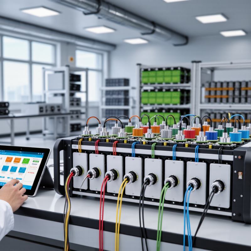
Look closely at the bench.
A credible selection process should examine calibration traceability, software logging, emergency protection, thermal integration, and service support. The U.S. Advanced Battery Consortium test procedures also demonstrate how controlled protocols improve comparison between laboratories. In real use, cable resistance, connector heating, and imperfect synchronization can distort results. A simulator that performs well on a datasheet may disappoint under continuous cycling. No system is perfect. The better question is whether its limitations are visible, measurable, and manageable. This guide explains how to compare specifications, verify supplier claims, and choose equipment that supports safe, repeatable battery research.
What Is a Multi-Channel Battery Cell Simulator?
A multi-channel battery cell simulator is a laboratory instrument for testing several cells under controlled electrical conditions. Each channel can source or sink current, while measuring voltage, current, and sometimes temperature. This allows engineers to reproduce charging, discharging, cycling, and fault scenarios without using a complete battery pack.
The channels usually operate independently, but they can also run synchronized test profiles. For example, one channel may apply a 2 A discharge while another holds a constant-voltage charge. Accurate sampling is essential here. A small voltage error can distort capacity calculations, especially during long cycling tests. Galvanic isolation, overvoltage protection, thermal monitoring, and emergency shutdown functions improve testing reliability.
In practical laboratory work, I would inspect channel consistency before trusting a large dataset. Connect identical reference loads and compare readings across channels. Small differences matter. A good simulator should provide stable control, clear data logging, adjustable limits, and calibration records linked to recognized measurement standards. Software usability also affects results; confusing menus can create avoidable operator errors. No setup is perfect. Cable resistance, sensor placement, and cell temperature can still influence measurements. That is why choosing a simulator requires more than counting channels. Consider current range, voltage resolution, response speed, synchronization, safety features, and the type of cells being tested. A system built for tiny laboratory cells may not suit high-current development work.
How to Choose a Multi Channel Battery Cell Simulator? - What Is a Multi-Channel Battery Cell Simulator?
| Selection Dimension | What It Means | Representative Technical Data | Recommended Choice | Why It Matters |
|---|---|---|---|---|
| Number of Channels | The number of battery cells that can be simulated independently at the same time. | Common configurations include 4, 8, 16, 32, 64, or more independent channels. | Choose 8–16 channels for general cell, BMS, and balancing tests; select more channels for high-throughput validation. | More channels increase test throughput and allow complete multi-cell battery-stack simulation. |
| Output Voltage Range | The voltage range that each simulated cell can reproduce. | Typical single-channel ranges are 0–5 V, 0–6 V, or 0–12 V; bipolar operation may be available on specialized systems. | Use a 0–6 V range for most lithium-ion cell emulation; select 0–12 V when testing higher-voltage cells or broad chemistries. | The maximum voltage must exceed the highest cell voltage required by the BMS and test profile. |
| Source and Sink Current | The ability to deliver current to or absorb current from the device under test. | Typical ranges are approximately ±5 A to ±100 A per channel, depending on power class and cooling design. | Select at least ±10 A for standard BMS testing; choose ±30 A or higher for dynamic load, fast-charge, or high-power validation. | Bidirectional current is essential for reproducing both charge and discharge behavior. |
| Per-Channel Power | The maximum electrical power that one channel can source or sink continuously. | Typical values range from approximately 30 W to 600 W per channel; some systems support higher pulsed power. | Calculate power as voltage × current and include a margin of at least 20% above the test requirement. | A sufficient power rating prevents clipping during transient events and high-current operating points. |
| Voltage Accuracy and Resolution | Accuracy describes the difference from the programmed value; resolution describes the smallest adjustable step. | Typical accuracy is about ±0.05% to ±0.1% of full scale, with voltage resolution from 0.1 mV to 1 mV. | For cell-monitoring and balancing tests, target voltage accuracy of ±0.05% full scale and resolution of 1 mV or better. | Fine voltage control helps verify balancing thresholds, overvoltage protection, and state-of-charge algorithms. |
| Current Accuracy and Resolution | Determines how precisely charge and discharge currents are reproduced and measured. | Typical current accuracy is ±0.05% to ±0.1% of full scale; resolution commonly ranges from 0.1 mA to 10 mA. | Choose the lowest practical current range for low-current balancing tests and a higher range for power-stage validation. | Poor current resolution can hide leakage, balancing, and quiescent-current behavior. |
| Dynamic Response and Slew Rate | How quickly the simulator can change voltage or current after a command or load transient. | Control-loop response may range from tens of microseconds to several milliseconds; programmable slew rates are often available. | Use a fast-response system for transient, fault-injection, and automotive BMS testing; a slower system may be sufficient for functional tests. | Fast dynamics improve the realism of sudden load changes, contactor events, and protection responses. |
| Operating Modes | The electrical behaviors and test profiles the simulator can reproduce. | Common modes include constant-voltage, constant-current, internal-resistance, programmable waveform, state-of-charge, and battery-model playback. | Select a system with programmable profiles and model-based operation when testing real-world drive cycles or BMS algorithms. | Flexible modes reduce the need for external equipment and support both basic and advanced validation. |
| Independent Channel Isolation | Electrical separation between channels and from the system ground. | Isolation ratings commonly range from several hundred volts to approximately 1,000 V, depending on the architecture. | Choose isolated channels for stacked-cell simulation, floating BMS inputs, and systems with non-ground-referenced connections. | Isolation prevents unintended current paths and enables realistic series-cell configurations. |
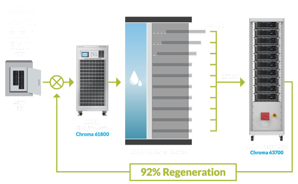
| Energy Recovery | The ability to return absorbed discharge energy to the facility supply instead of dissipating it as heat. | Regenerative efficiency is commonly around 70%–95%, subject to operating voltage, current, and system design. | Choose regenerative operation for high-current, long-duration, or multi-channel testing. | Energy recovery can reduce facility power consumption, heat output, and cooling requirements. |
| Communication and Automation | The interfaces used to configure tests, control channels, and collect measurements. | Common interfaces include USB, Ethernet, CAN, RS-485, analog I/O, and standardized command protocols. | Select Ethernet or USB for laboratory automation and CAN or isolated I/O when integrating with automotive BMS hardware. | Open interfaces simplify integration with test benches, data-acquisition systems, and automated test software. |
| Protection Functions | Built-in safeguards that protect the simulator, BMS, wiring, and connected equipment. | Important protections include overvoltage, overcurrent, overtemperature, short circuit, reverse polarity, isolation fault, and emergency stop. | Choose independently configurable limits, fast shutdown, event logging, and external interlock support. | Protection features reduce the risk of damage during wiring errors, abnormal BMS commands, and fault tests. |
| Thermal Management | The method used to remove heat generated during power conversion. | Low-power units may use forced air; higher-power multi-channel systems may require enhanced airflow or liquid cooling. | Match the cooling method to continuous power, ambient temperature, acoustic limits, and installation space. | Stable thermal performance helps maintain measurement accuracy and prevents power derating. |
| Calibration and Data Logging | The ability to verify measurement accuracy and record test results for later analysis. | Useful functions include traceable calibration intervals, timestamped voltage/current data, alarm records, and exportable files. | Choose automated logging with configurable sample rates and calibration documentation for compliance-oriented testing. | Reliable records support repeatability, troubleshooting, qualification, and audit requirements. |
| Typical Application Fit | The test category the simulator is best suited to support. | Common applications include BMS functional testing, cell-balancing verification, SOC/SOH algorithm validation, charger testing, fault injection, and end-of-line test development. | Define the required voltage, current, response time, channel count, and automation interfaces before selecting a model. | A properly matched simulator provides realistic cell behavior without using physical cells for every development iteration. |
Note: The technical figures shown are representative ranges commonly found in multi-channel battery cell simulators. Actual specifications vary by system architecture, channel power rating, cooling method, and operating conditions.
FAQS
Choose independent channel protection, overvoltage limits, current limits, and thermal monitoring. Emergency shutdown should respond quickly to abnormal cell behavior. Galvanic isolation helps prevent one channel fault from spreading. Clear alarm records make troubleshooting easier. Small details matter.
Isolation reduces fault propagation between connected channels. If one cell behaves unexpectedly, other channels remain better protected. Confirm the isolation rating and test conditions. Do not rely on appearance alone.
Check voltage accuracy across the complete operating range. Review current stability during rapid charge and discharge changes. Ask for calibration records, uncertainty values, and temperature-drift data. A clean waveform can still hide measurement errors.
Each channel should support separate voltage, current, timing, and profile settings. Synchronized control helps reproduce pack-level events. Flexible scripts support repeated fault and recovery tests. Manual intervention remains useful. Automation can miss assumptions.
Data logs should include timestamps, channel status, alarms, measured values, and calibration status. Raw exports help engineers compare cells without separate spreadsheets. Test your own profile before purchasing. A simple demonstration may not represent a long cycling schedule.
Remote access can reduce routine work and improve monitoring. It should include permission controls and reliable connection recovery. Manual control should remain available when a sequence behaves unexpectedly. Convenience is helpful, but recovery matters more.
Confirm whether added channels require controllers, licenses, racks, cooling, wiring, or facility upgrades. Review capacity, isolation, and communication limits. Calculate the cost of adding channels after two years. Modular equipment is not automatically economical.
Include installation, training, calibration, maintenance, energy use, software support, and expansion costs. Request conservative assumptions and mark uncertain figures clearly. Some estimates will be wrong. Service records provide stronger evidence than attractive projections.
Conclusion
Choosing the right Multi-Channel Battery Cell Simulator begins with understanding its role in battery research, development, validation, and production testing. These systems allow multiple cells or channels to be tested independently or simultaneously under controlled voltage and current conditions. Selection should be guided by key testing requirements, including the number of channels, cell chemistry, voltage range, charge and discharge current, measurement resolution, and the need for synchronized or flexible test profiles.
Safety, accuracy, and control features are equally important. Look for reliable protection against overvoltage, overcurrent, overheating, and connection errors, along with precise monitoring and stable performance. User-friendly software should support test programming, data recording, real-time analysis, and automated reporting. It is also helpful to evaluate communication options, system expansion, maintenance needs, and long-term operating costs. A careful comparison of technical capabilities, software functionality, scalability, and total ownership cost will help ensure the simulator meets both current testing demands and future development goals.