
Power Electronics & Test Technical Knowledge Base
Explore technical articles, industry insights, and power testing innovations from Chroma engineering experts.
Why Choose a Battery Pack Power HIL Testbed?
Battery packs rarely fail in neat, predictable ways. Cell imbalance, temperature shifts, contact resistance, and sudden load changes can alter performance within seconds. A Battery Pack Power HIL Testbed helps engineers reproduce these conditions while connecting real battery hardware to a real-time simulated environment. The setup can expose a pack to repeatable power demands without relying on full vehicle trials for every test.
Battery modeling researcher Dr. Gregory Plett is a relevant authority on battery behavior and estimation. A widely cited testing principle comes from statistician George Box: “All models are wrong, but some are useful.” It captures an important HIL challenge: simulation is valuable only when its assumptions are checked against measured pack behavior. A testbed can compare simulated signals with live voltage, current, and temperature readings, helping teams find mismatches before they become expensive surprises.
The practical benefit is control. Engineers can adjust load profiles, inject faults, and observe how the battery management system responds. They can repeat a cold-start test on Monday and compare it with the same profile on Friday. Consistency matters.
But the bench is not the road. Wiring, sensor placement, and model fidelity can still distort results. Engineers must document those limits and validate findings against physical tests. A Battery Pack Power HIL Testbed is not a shortcut around engineering judgment. It is a way to make that judgment more measurable, repeatable, and easier to challenge.
What a Battery Pack Power HIL Testbed Is
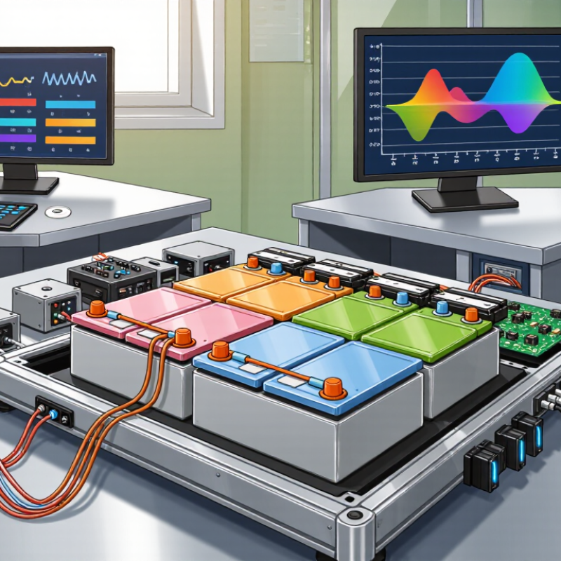
A battery pack power HIL testbed links real battery hardware to a real-time simulation system. HIL means hardware-in-the-loop. The pack, or a representative section, exchanges electrical power with a programmable interface while the simulator recreates conditions such as changing motor demand, charging, or temperature. Sensors and control units report measurements during each test.
The setup can include power converters, voltage and current measurement, temperature sensors, protective interlocks, and software that models a vehicle or energy system. Engineers can observe how the battery management system responds to sudden load changes, cell imbalance, or a sensor fault. The test can be repeated with the same settings. That helps make results easier to compare, though models still simplify reality.
Details matter. Cable resistance, switching delays, and thermal behavior can change what the system sees. A HIL result is not proof that every real-world condition has been covered. Teams need to document model limits, verify measurement accuracy, and define safe operating boundaries before applying power. Some setups are less representative than they appear. That deserves a second look.
How a Battery Pack Power HIL Testbed Operates
A battery pack power HIL testbed closes the control loop between a real battery management system (BMS) and a simulated pack. A real-time simulator calculates cell voltages, temperatures, and pack behavior from a driving or charging scenario. A bidirectional power amplifier then supplies or absorbs current, reproducing the pack’s electrical response. Meanwhile, the BMS measures simulated signals and returns commands, such as contactor or current-limit requests. That loop matters. The International Energy Agency’s Global EV Outlook 2024 reports nearly 14 million electric-car sales in 2023, around 18% of global car sales. Reliable, repeatable battery control testing is increasingly important.
Engineers can introduce a weak cell, a sudden load change, or a sensor fault without waiting for those conditions to occur in a physical pack. They watch the voltage trace, current response, and BMS decisions in real time, then replay the same event after a software change. Small delays matter. A testbed can expose unstable control behavior before road or bench testing, while limiting the need to use a full battery pack for every iteration. Yet no model is the pack. Cell aging, wiring resistance, and thermal differences can be hard to reproduce perfectly, so results still need comparison with physical tests. That limitation is easy to underestimate.
Key Benefits for Battery Development and Validation
A battery pack power hardware-in-the-loop (HIL) testbed connects real battery hardware and control units to simulated loads. Engineers can examine voltage sag during acceleration, contactor transitions, thermal derating, and communication faults without repeating every test on a complete vehicle. That matters as development cycles tighten. The International Energy Agency’s Global EV Outlook 2024 reports that electric-vehicle battery demand reached about 750 GWh in 2023, roughly 40% above 2022. More battery capacity means more configurations to validate.
Repeatable tests are a key benefit. Teams can replay the same load profile, change one control parameter, and compare cell-level voltage, pack current, and temperature traces. They can also probe protection limits and state-of-charge estimates under carefully controlled conditions. Real tests are costly. Still, HIL is not a substitute for physical validation: an inaccurate battery model can produce convincing but misleading results. Engineers should correlate simulations against measured pack data, document model assumptions, and revisit them as cells age or hardware changes. That discipline takes time, and it is easy to underestimate.
Applications Across Battery Testing and Control
A battery pack Power HIL testbed lets engineers test control systems against a simulated battery while exchanging real electrical power. It is useful when a physical pack is costly, unavailable, or not yet safe to stress. A bench setup can reproduce voltage and current changes during acceleration, regenerative braking, or charging. The battery management system responds in real time, so engineers can observe contactor commands, current limits, and protection behavior.
Applications span battery testing and control development. Teams can compare state-of-charge estimates with known model values, then examine errors during rapid load changes. They can also test charging strategies across different temperatures and battery conditions. Fault scenarios, such as a sensor signal dropping out, can reveal whether the controller reacts as intended. Results depend on model quality, though; a tidy simulation can still miss details of real cells.
Tips: Set clear voltage, current, and temperature limits before testing. Log both commanded and measured signals, including brief transients. Repeat key tests with varied starting conditions. One limitation is easy to overlook: model assumptions should be checked against physical measurements, not treated as ground truth.
Why Choose a Battery Pack Power HIL Testbed?
Representative battery-pack load-step test: compare commanded current with the response measured by a hardware-in-the-loop (HIL) setup.
This illustrative profile shows how a HIL testbed can exercise battery-management controls under changing loads and help evaluate current tracking and transient response. Values are representative, not benchmark results.
Factors to Consider When Choosing a Testbed
Why Choose a Battery Pack Power HIL Testbed?
A useful testbed should reproduce the battery pack’s real electrical limits, not just its nominal voltage. Check continuous and peak power, current range, regenerative energy handling, and measurement accuracy. The IEA’s Global EV Outlook 2024 reports that electric-vehicle battery demand reached about 750 GWh in 2023, roughly 40% above 2022. That growth makes repeatable validation more important. Small errors matter.
Match the testbed’s response speed to the events you need to simulate, such as rapid torque requests or sudden load changes. Confirm that its real-time controller can run your vehicle model without missed steps. Also check channel count, sensor interfaces, fault injection, and whether the setup can expand from a cell or module to a full pack. A tidy specification sheet can still hide integration work.
Safety and usable power deserve equal attention. Look for interlocks, emergency shutdown, isolation monitoring, and clear procedures for handling stored energy. Ask how the system behaves during a communication loss or over-temperature event. I would not choose capacity with no headroom; future pack revisions may exceed today’s test limits. Yet oversizing can waste budget and floor space. Measure your actual voltage, current, and transient needs before comparing testbed ratings.
Why Choose a Battery Pack Power HIL Testbed? - Factors to Consider When Choosing a Testbed
| Selection Factor | What to Evaluate | Typical Planning Considerations | Why It Matters |
|---|---|---|---|
| Voltage range | Maximum and minimum pack voltage, including operating and transient conditions | Choose a system rated for the intended battery architecture; testbeds may cover low-voltage systems around 48 V or high-voltage systems in the several-hundred-volt range. | Insufficient voltage capability can limit test coverage and prevent testing across the pack’s full operating range. |
| Power and current capacity | Continuous and peak charge/discharge power, current, and duration | Size the power stage from the pack’s maximum test profile. For example, 50 kW at 500 V corresponds to approximately 100 A, before considering losses and operating margins. | Correct sizing supports representative load profiles while avoiding unnecessary equipment cost and capacity. |
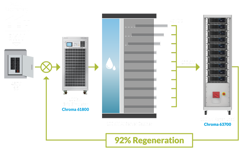
| Bidirectional operation | Whether the system can both source power to and absorb power from the device under test | Consider regenerative operation and the facility’s ability to handle returned energy, such as grid regeneration or an appropriate energy sink. | Bidirectional capability enables charge and discharge testing and can reduce wasted energy during repeated cycles. |
| Real-time simulation | Simulation time step, model execution time, and deterministic communication | Set timing requirements according to the control functions under test. Fast electrical or switching-related studies may need shorter time steps than slower supervisory-control tests. | Accurate, repeatable timing is essential for evaluating controller response and interaction with simulated battery behavior. |
| Battery model fidelity | Representation of state of charge, voltage response, temperature effects, aging, and fault behavior | Match model complexity to the test objective; validate model parameters against relevant cell, module, or pack data where available. | A suitable model improves the relevance of test results without adding complexity that the application does not need. |
| BMS interface compatibility | Support for required analog, digital, and network interfaces | Confirm signal levels, channel counts, isolation, timing, and protocol support for interfaces such as CAN or automotive Ethernet when required. | Compatible interfaces allow the battery management system to interact with the testbed as it would with the intended system. |
| Measurement and I/O | Voltage and current accuracy, sampling rate, synchronization, and available I/O channels | Specify measurement ranges and accuracy based on the acceptance criteria and expected signal bandwidth. | Reliable, synchronized measurements make results easier to compare, diagnose, and reproduce. |
| Protection and safety | Overvoltage, overcurrent, insulation monitoring, interlocks, emergency stop, and fault handling | Review protection coordination, isolation ratings, safe shutdown behavior, and site requirements for high-voltage testing. | Layered safeguards help protect personnel, the device under test, and the test equipment during normal operation and fault conditions. |
| Thermal and environmental coverage | Temperature range, thermal modeling, and compatibility with external environmental equipment | Determine whether testing needs a simulated thermal model, physical conditioning equipment, or both. | Battery performance and limits depend on temperature, so thermal coverage can be important for representative validation. |
| Scalability and integration | Ability to add power capacity, channels, test automation, and data-management tools | Check modular expansion options, software interfaces, facility power, cooling, and space requirements before installation. | A scalable setup can accommodate changing test programs and reduce the need for major system replacement. |
Note: Values and examples are general planning guidance, not a specification for a particular testbed. Confirm ratings, measurement performance, safety provisions, and facility requirements against the battery pack and test plan.
FAQS
It links a real battery management system to a simulated battery pack. The testbed reproduces electrical behavior.
A real-time simulator calculates cell voltage, temperature, and pack behavior. A bidirectional amplifier supplies or absorbs current.
They can monitor cell voltage, pack current, temperature, and control decisions. A voltage trace can reveal a sudden dip.
They can introduce a weak cell, a changing load, or a sensor fault. No real fault is needed.
Teams can replay the same load profile after changing a control setting. That makes comparisons clearer, though not effortless.
No. Models may miss aging, wiring resistance, or thermal differences. Models are not cells.
They should compare results with measured pack data, document assumptions, and update models when cells or hardware change.
It can show voltage sag during acceleration, contactor transitions, thermal derating, and communication faults. Small delays matter.
Conclusion
A Battery Pack Power HIL Testbed connects a physical battery pack or related hardware to a real-time simulation environment. It allows engineers to evaluate how battery systems, control logic, and simulated operating conditions interact without relying solely on tests in a complete vehicle or energy system. By combining measured signals with simulated scenarios, the testbed can help reproduce changing loads and operating conditions in a controlled setting.
This approach supports battery development and validation by making it easier to assess performance, monitor system responses, and identify potential issues early. It can be used to test battery management strategies, power control, and responses to different operating demands. When choosing a testbed, consider its power and voltage range, measurement accuracy, real-time capabilities, safety features, flexibility, and compatibility with existing equipment and workflows. Selecting a setup that matches the intended applications can make testing more relevant, repeatable, and useful throughout the development process.

Blog Tags: